JEL phono and line preamps
12 Jan 2011 à 00:41
Bonjour,
je souhaiterai monter ce phono, mais j'ai quelque doute sur l'alim et les condos tampons concernant la constante de temps vu qu'il est pour du 60 hertz, j' ai essayé de calculer mais trop complexe pour moi. quelqu'un peut-être pour m'expliquer ? merci.
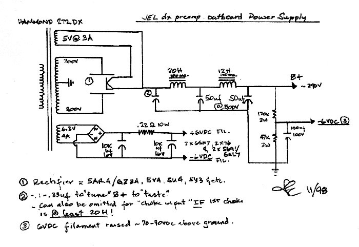
Voilà le schéma.
En espérant que se post serra très constructif pour tous.
Franz.
je souhaiterai monter ce phono, mais j'ai quelque doute sur l'alim et les condos tampons concernant la constante de temps vu qu'il est pour du 60 hertz, j' ai essayé de calculer mais trop complexe pour moi.
Voilà le schéma.
Cliquez sur l'image pour l'agrandir
Cliquez sur l'image pour l'agrandir

Cliquez sur l'image pour l'agrandir
En espérant que se post serra très constructif pour tous.
Franz.
Re: JEL phono and line preamps
14 Jan 2011 à 22:11
On voit la différence entre le vert et le blanc.
Au revoir.
Au revoir.
Re: JEL phono and line preamps
14 Jan 2011 à 23:14
807se » 14 Jan 2011, 21:11 a écrit:On voit la différence entre le vert et le blanc.
Au revoir.
Bah... moi je sais pas te répondre en tout cas.
J'avais lorgné sur ce schéma style RCA aussi, mais j'ai du mal à me lancer sur le phono...
B r u n o
Re: JEL phono and line preamps
15 Jan 2011 à 00:11
Salut Bruno, je suppose que c'est la pile qui te gêne, sur la 26 j'ai remplacé RK par une pile de 9v, ça marche très bien, ça réduit le bruit et les basses ont + de matière.
Franz.
Franz.
Re: JEL phono and line preamps
15 Jan 2011 à 10:22
Les infos qu'il me faut en premier :
la résistance interne du transfo, comment on la calcule ?
Hammond 372DX : Power: 127 W
Sec. 1: 300-0-300 V @ 125 mA DC
Sec. 2: 5 V CT @ 3 A
Sec. 3: 6,3 V CT @ 4 A
Si j'ai bien décodé les datas de la diode 80, 50 ohm par plaque sou 350v, pour 300v par plaque, va t-elle changer, comment on la calcule ?
http://www.r-type.org/pdfs/80.pdf
Franz.
Re: JEL phono and line preamps
15 Jan 2011 à 11:06
807se » 12 Jan 2011, 00:41 a écrit:Bonjour,
je souhaiterai monter ce phono, mais j'ai quelque doute sur l'alim et les condos tampons concernant la constante de temps vu qu'il est pour du 60 hertz, j' ai essayé de calculer mais trop complexe pour moi.
Salut Franz,
Pourquoi n'essaie-tu pas de contacter directement Joseph ESMILLA
je245(at)myactv.net
Re: JEL phono and line preamps
19 Jan 2011 à 23:34
Personne pour me donner un coup de main. 


Franz.
Franz.
Re: JEL phono and line preamps
20 Jan 2011 à 00:43
essaie, tu verras bien... Tu pourras toujours changer les condos ou même la diode ensuite.
Je crois que ce schéma est classique mais pas extraordinaire, si je me rappelle ce que Kevin Kennedy en a dit.
Graham est de ce point de vu, et me pousse à faire le Siren Song de Morrison, mais en modifiant son alim (qui n'est pas très stable), pas simple pour moi...
Par contre il m'a convaincu avec les TV tubes damper, meilleur grave, meilleure image, impédance de sortie plus basse, moins de chute de tension (le mix TV damper et diodes que j'utilise sur le 26 marche le mieux, meilleur grave).
B r u n o
Re: JEL phono and line preamps
20 Jan 2011 à 10:33
807se » 15 Jan 2011, 10:22 a écrit:Les infos qu'il me faut en premier :
la résistance interne du transfo, comment on la calcule ?
Hammond 372DX : Power: 127 W
Sec. 1: 300-0-300 V @ 125 mA DC
Sec. 2: 5 V CT @ 3 A
Sec. 3: 6,3 V CT @ 4 A
Si j'ai bien décodé les datas de la diode 80, 50 ohm par plaque sou 350v, pour 300v par plaque, va t-elle changer, comment on la calcule ?
http://www.r-type.org/pdfs/80.pdf
Franz.
Salut Franz,
c´est la résistance interne ou la résistance équivalente du montage que tu veux?
La résistance du transfo pour l´association avec ton ta valve redresseuse:
Minimum Limiting Resistance: A valve rectifiers must have a resistance in series with each anode. Many 'classic' amps do not include these when they ought to, and rectifier failure is common in these amps. The data sheet will provide a Minimum Limiting Resistance (Rlim(min)) for different supply voltages, although the limiting resistance can be decreased if the reservoir capacitor is also decreased proportionately. Part of the limitng resistance will be made up of unavoidable transformer resistance and reflected impedance, and this should be calculated first in order to find out whether any additonal resistance must be added.
For example, when supplied by a transformer rated at 300-0-300Vrms, the EZ80 specifies Rlim(min) = 215 ohms per anode. The total impedance presented to the rectifier by the transformer is given by:
Rt= Rs + (n^2)* Rp
Where:
Rs = DC resistance of one half of the transformer secondary winding.)
Rp = DC resistance of the transformer primary winding.
n = Secondary to primary turns ratio (equal to the secondary voltage divided by the primary supply voltage).
If we were using a mains transformer with a 240V; 80R primary and a 310-0-310V; 50R per half secondary:
Rt= 50 + (1.29^2)* 80 = 183R
The EZ80 requires at least 215 ohms, so an additonal 215 - 183 = 32 ohm resistor must be placed in series with each anode (so we would probably use 33 or 47 ohms).
Because the limiting resistors will have to carry the ripple current of the reservoir capacitor it is best to use high wattage resistors. Even 7W resistors will usually get quite warm. Remember that the voltage drop across the limiting resistors will cause the HT fall proportionately.
Alternatively, a single limiting resistor could be placed between the transformer centre tap and ground, although its power dissipation will be doubled.
Clearly your choice of rectifier has a huge effect on the HT you ultimately achieve. It is the voltage drop across the rectifier and series limiting resistance that causes 'sag' in Class-AB amps. When a loud sound is played and the amp suddenly draws more current the voltage dropped across the rectifier increases, lowering the HT and creating a compressing effect known as 'sag'. Class-A amps do not exhibit this effect since their current draw remains constant on average. Silicon diodes have a voltage drop (about 0.7V) that is constant with current so they do not produce sag, but it can be simulated simply be placing a resistor (roughly 100R to 330R) in series with the rectifier. But be sure to calculate the necessary power rating! A resistor in this position will usually need to be the biggest one in the amplifier, and may need to be rated at 10W or more.
Trouvé ici:
http://www.freewebs.com/valvewizard/fullwave.html
Pour calculer la résistance équivalente de ton ampli, c´est le rapport entre la tension d´alim en V et le courant au repos en mA.
Vincent